


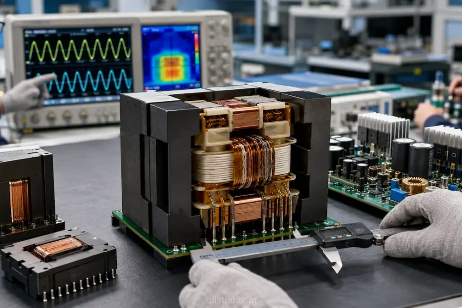
An LLC resonant converter can look efficient on the schematic and still become difficult to stabilize once the magnetic design moves into hardware.
The transformer is part of that problem.
Turns ratio, magnetizing inductance, leakage inductance, core material and winding structure all affect how the resonant tank behaves. If the transformer is treated as a simple isolation component, the prototype may end up with unexpected losses, excessive temperature rise or a switching range that does not match the original design.
TrafoPSU’s EER42 LLC Resonant Transformer is built around an EER42 ferrite core with a reference power of 1000W. The product page lists operation from 60 to 200kHz, with a nominal resonant frequency of 100kHz, and supports customization of turns ratio, Lm/Lr targets, wire gauge and winding topology.
For an engineer, those parameters need to be considered together.
A change in turns ratio affects voltage conversion, but it can also alter winding arrangement and copper loss. Magnetizing inductance influences circulating current, while leakage inductance may become part of the resonant network instead of being treated purely as a parasitic value.
Sample approval should therefore include more than checking output voltage.
I would measure primary current, resonant waveforms, switching behavior, transformer temperature and efficiency across the intended operating range. Testing should cover more than the rated-power point, because LLC operating conditions can change significantly as the load changes.
Layout and mechanical constraints matter too.
TrafoPSU notes that the EER42 platform can be customized for vertical or horizontal mounting, pin mapping and PCB requirements. Those details should be frozen early because a winding solution that works electrically may become difficult to manufacture if the PCB footprint or pin arrangement changes late in the project.
If the converter is expected to operate far from the nominal 100kHz point, core loss and temperature rise should also be checked under those actual switching conditions rather than assumed to remain unchanged.
The broader TrafoPSU website covers SMPS transformers, planar transformers, inductors, chokes and other custom magnetic components for power electronics.
For an integrated LLC resonant transformer, the useful specification is not simply “1kW, 400V input.” The magnetic design has to match the resonant tank, thermal limits, PCB layout and switching range of the actual converter.
